


Pulsed Output Modification:
For Use With Netafim Aquanet Plus Pulsed Valves
The Netafim Aquanet Plus 12-40 VDC Valves and 18-28VAC Valves are compatible with most DC latch controllers with two wire output.
The Aquanet Plus valves need an 80ms pulse to Open and then a polarity swap with another 80ms pulse to close. This makes them ideal for irrigation projects due to their low energy consumption, support for extended cable lengths, and reliable operation.
-
Low energy consumption, allowing maximum cable lengths ensuring minimal energy consumption and reliable operation.
-
They are essentially an electric/hydraulic control valve operating at high flow rates, while operating at low head loss.
-
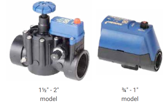
They come in two models: 1” and 2”, available in both AC and DC (latch) versions. The 2” valve has an integral pressure regulator (range 0.7 – 4.5 bar). All Aquanet Plus valves are also equipped with integral flow rate control and manual operation so that they can be opened and closed independently of the controller.
-
Suitable for landscape and greenhouse applications.
|

|
|---|
DATA SHEET: aquanet-electric-valves-page.pdf
How Can We Modify Ladybird To Provide A Pulsed Output?
To generate the required pulsed output for controlling the valves, the Ladybird system can be modified using two UNI 4M multifunction timers. This setup replicates the polarity-reversing pulse needed to operate the Netafim Aquanet Plus valves..

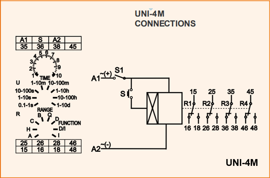
The first module must be configured to operate in Function I mode, acting as a pulsed changeover relay that reverses the polarity of the DC signal supplied to the valve. When Ve+ is applied to the valve’s positive terminal and Ve− to its negative terminal for a minimum duration of 80 milliseconds, the valve will open. Reversing this polarity will cause the valve to close.
Function I:
Latching relay “pulse on, pulse off.’ via trigger input.
A continuous supply must be maintained at terminals A1 and A2, although control is governed by the trigger input on terminal S. The controlling factor is a trigger input from A1 onto terminal S.
On an input being made to terminal S the relay contacts will immediately Energise
On a new trigger input the relay contacts will immediately de-energise.
In brief the unit works as a “pulse on, pulse off’ relay.
The second module must be configured to operate in Function H mode, acting as a pulsed ON/OFF for the DC signal supplied to the valve. Depending on which polarity is supplied to its terminals 15 and 25 will determine the power to the valves + and - terminals.
Function H:
Interval timer - initiated by supply on terminals A1 & A2.
Relay contacts energise immediately on connection of the supply.
On completion of timing set to 0.1 to 1 second, the relay contacts de-energise.
If the supply is removed during the timing period the relay
contacts will de-energise immediately. The feed to A1 is via a switched relay contact 45 fed from The latching pulsed On / pulsed Off relay that is set to Function I Mode.
⚡ Electrical Wiring Logic Review
The described logic above matches the operational requirements of the Netafim Aquanet Plus valves:
-
Function I (Latching Relay): Controls polarity switching via 30 second pulse input.
-
Function H (Timed Pulse): Provides the 80ms pulse duration.
-
Polarity Reversal: Achieved by toggling the relay states in sequence.
-
Ladybird Signal Timing: 30s ON signal ensures reliable triggering and avoids premature switching.
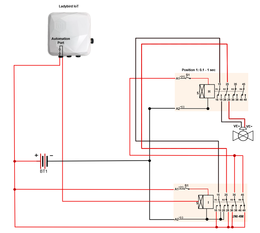
Ladybird Initial Connections - On initial connection the Ladybird and the two relay modules will be found in the following state.
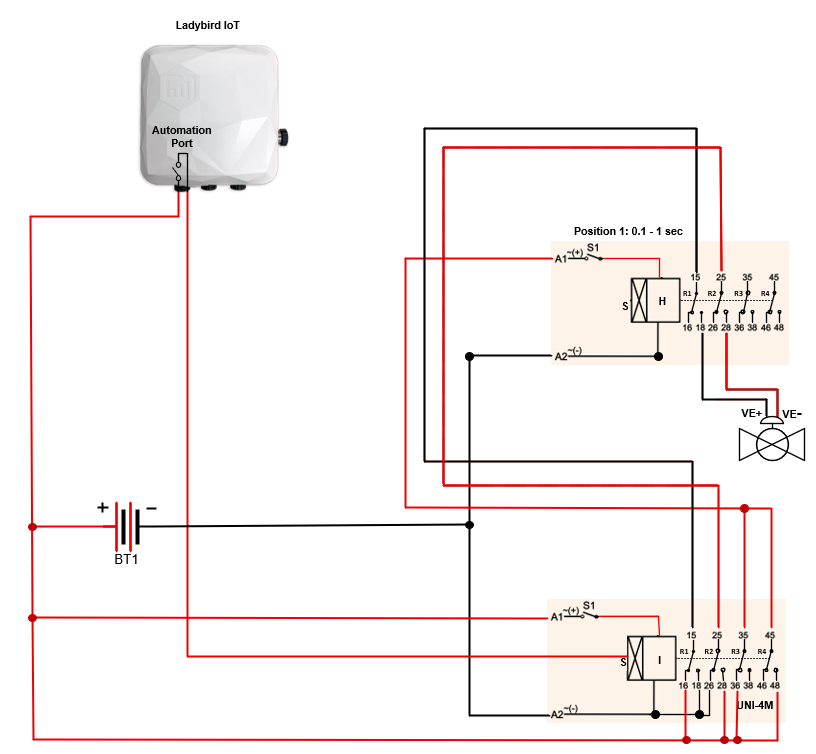
Ladybird First Automation On Signal - The Ladybird must initiate a minimum 30-second ON signal to verify correct wiring and ensure the valve closes. The drawing below will show the colours of the wiring changing polarity as the latching timer changes state Ve+ is applied to the valve’s negative terminal and Ve− to the valves positive terminal for a minimum duration of 80 milliseconds and then the timed module set to Function H Mode will de-energise its relays whilst the latching relay set to Function I Mode its relays will remain energised until the next signal on S.
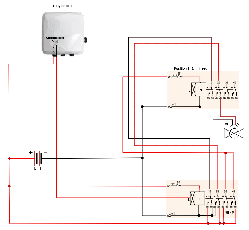
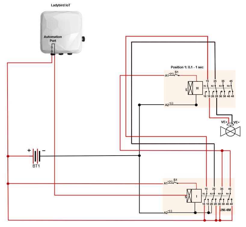
After 80ms Minimum - The the top multifunction timer can be seen to de-energise its relays after circa 80ms even though the Ladybird Automation contact is still closed.
"Ladybird Signal to Open Valve" To close the valve, the Ladybird must first de-energise its output signal, which should occur automatically after maintaining an ON state for a minimum of 30 seconds, as configured in the Ladybird Dashboard. The subsequent scheduled ON signal will then cause the lower multifunction module to de-energise, closing its relay contacts. This action reverses the DC polarity applied to the upper timed multifunction module, enabling Ve+ to be applied to the valve’s positive terminal and Ve− to its negative terminal. When this condition is maintained for at least 80 milliseconds, the valve will open.
Ladybird Resting State After 80ms the top relay will de-energise and after 30 seconds, the Ladybird will open its contact leaving the irrigation valve in an open state irrigating the field or greenhouse.
"Ladybird Signal to Close Valve" To close the valve, the Ladybird must re-energise its output signal and maintain it for a minimum of 30 seconds. Following this, the next scheduled ON signal will cause the lower multifunction module to energise, closing its relay contacts. This action reverses the DC polarity applied to the upper timed multifunction module, allowing Ve+ to be applied to the valve’s negative terminal and Ve− to its positive terminal. When this condition is sustained for at least 80 milliseconds, the valve will close